Ask Latest Price
Active Member
7 Years

Zhejiang TongJiang Holdings Company
Corporate Philosophy: Concentrate on Valve Industry, Serve our customers Corporate Vision: To be the first class valve industry


Add to Cart
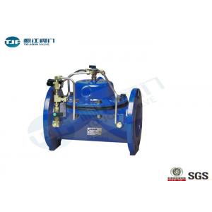
Water Hydraulic Control Valve in Diaphragm Types, Cast Iron, ANSI 150 LB
PRODUCT INTRODUCTION
1. Description
The Model 100-01 Hytrol Valve is a hydraulically operated, diaphragm actuated, globe or angle pattern valve. It consists of three major components: body, diaphragm assembly, and cover. The diaphragm assembly is the only moving part.The diaphragm assembly is guided top and bottom by a precision machined stem. It utilizes a non-wicking diaphragm of nylon fabric bonded with synthetic rubber. A resilient synthetic rubber disc retained on three and one half sides by a disc retainer forms a drip-tight seal with the renewable seat when pressure is applied above the diaphragm.
The Model 100-01 is the basic valve used in nearly all Automatic Control Valves. It is the valve of choice for system applications requiring remote control, pressure regulation, solenoid operation, rate of flow control, liquid level control or check valve operation. The rugged simplicity of design and packless construction assure a long life of dependable, trouble- free operation. It is available in various materials and in a full range of sizes, with either threaded, flanged or grooved ends. Its applications are unlimited.
The direct sealing diaphragm valves is operated by the pressure of the pipeline and is used for various control applications in water supply, fire protection, industrial, sewage and irrigation systems.
The only moving component is a reinforced diaphragm, which:
Drip tight seals the liquid passage in the closed valve
Allows free passage in the fully open valve with minimal obstruction to the flow line
Throttles the flow passage in the modulating valve, as dictated by the pressure in the control chamber
2. Features and Advantage
Structural simplicity
Exquisite design featuring exceptionally low pressure losses at high flow rates
Can be used for regulating from no-flow to maximal flow with no need for additional throttling devices or by-pass valves
For natural liquids, sea water and industrial effluents
A wide selection of materials, coating and diaphragm types
All valve models fit a wide variety of control applications using pilot valve
3. Specification
Available Sizes
| Pattern | Threaded | Flanged | Grooved End |
| Globe | 3⁄8" - 3" | 11⁄2" - 36" | 11⁄2"-2"- 21⁄2"- 3"- 4"- 6"- 8" |
| Angle | 1" - 3" | 11⁄2" - 16" & 24" | 2" - 3" - 4" |
Pressure Ratings
| Valve Body & Cover | Pressure Class | |||||
| Flanged | Grooved | Threaded | ||||
| Grade | Material | ANSI Standards* | 150 Class | 300 Class | 300 Class | End‡ Details |
| ASTM A536 | Ductile Iron | B16.42 | 250 | 400 | 400 | 400 |
| ASTM A216-WCB | Cast Steel | B16.5 | 285 | 400 | 400 | 400 |
| UNS 87850 | Bronze | B16.24 | 225 | 400 | 400 | 400 |
| Note: * ANSI standards are for flange dimensions only. Flanged valves are available faced but not drilled. End Details machined to ANSI B2.1 specifications. Valves for higher pressure are available; consult factory for details | ||||||
4. Hydraulic Control Valve Outsize Drawing

| Valve Size (Inches) | 3⁄8 * | 1⁄2 * | 3⁄4 * | 1 * | 1 | 1 1⁄4 | 1 1⁄2 | 2 | 2 1⁄2 | 3 | 4 | 6 | 8 | 10 | 12 | 14 | 16 | 18 | 20 | 24 |
| A Threaded | 2.75 | 3.50 | 3.50 | 5.12 | 7.25 | 7.25 | 7.25 | 9.38 | 11.00 | 12.50 | — | — | — | — | — | — | — | — | — | — |
| AA 150 ANSI | — | — | — | — | — | — | 8.50 | 9.38 | 11.00 | 12.00 | 15.00 | 20.00 | 25.38 | 29.75 | 34.00 | 39.00 | 41.38 | 46.00 | 52.00 | 61.50 |
| AAA 300 ANSI | — | — | — | — | — | — | 9.00 | 10.00 | 11.62 | 13.25 | 15.62 | 21.00 | 26.38 | 31.12 | 35.50 | 40.50 | 43.50 | 47.64 | 53.62 | 63.24 |
| AAAA Grooved End | — | — | — | — | — | — | 8.50 | 9.00 | 11.00 | 12.50 | 15.00 | 20.00 | 25.38 | — | — | — | — | — | — | — |
| B Diameter | 2.50 | 3.12 | 3.12 | 4.38 | 5.62 | 5.62 | 5.62 | 6.62 | 8.00 | 9.12 | 11.50 | 15.75 | 20.00 | 23.62 | 28.00 | 32.75 | 35.50 | 41.50 | 45.00 | 53.16 |
| C Maximum | 2.33 | 5.88 | 5.88 | 6.25 | 5.50 | 5.50 | 5.50 | 6.50 | 7.56 | 8.19 | 10.62 | 13.38 | 16.00 | 17.12 | 20.88 | 24.19 | 25.00 | 39.06 | 41.90 | 43.93 |
| CC Maximum Grooved End | — | — | — | — | — | — | 4.75 | 5.75 | 6.88 | 7.25 | 9.31 | 12.12 | 14.62 | — | — | — | — | — | — | — |
| D Threaded | — | — | — | — | 3.25 | 3.25 | 3.25 | 4.75 | 5.50 | 6.25 | — | — | — | — | — | — | — | — | — | — |
| DD 150 ANSI | — | — | — | — | — | — | 4.00 | 4.75 | 5.50 | 6.00 | 7.50 | 10.00 | 12.69 | 14.88 | 17.00 | 19.50 | 20.81 | — | — | 30.75 |
| DDD 300 ANSI | — | — | — | — | — | — | 4.25 | 5.00 | 5.88 | 6.38 | 7.88 | 10.50 | 13.25 | 15.56 | 17.75 | 20.25 | 21.62 | — | — | 31.62 |
| DDDD Grooved End | — | — | — | — | — | — | — | 4.75 | — | 6.00 | 7.50 | — | — | — | — | — | — | — | — | — |
| E | 1.25 | 0.88 | 0.88 | 1.63 | 1.12 | 1.12 | 1.12 | 1.50 | 1.69 | 2.06 | 3.19 | 4.31 | 5.31 | 9.25 | 10.75 | 12.62 | 15.50 | 12.95 | 15.00 | 17.75 |
| EE Grooved End | — | — | — | — | — | — | 2.00 | 2.50 | 2.88 | 3.12 | 4.25 | 6.00 | 7.56 | — | — | — | — | — | — | — |
| F 150 ANSI | — | — | — | — | — | — | 2.50 | 3.00 | 3.50 | 3.75 | 4.50 | 5.50 | 6.75 | 8.00 | 9.50 | 10.50 | 11.75 | 15.00 | 16.50 | 19.25 |
| FF 300 ANSI | — | — | — | — | — | — | 3.06 | 3.25 | 3.75 | 4.13 | 5.00 | 6.25 | 7.50 | 8.75 | 10.25 | 11.50 | 12.75 | 15.00 | 16.50 | 19.25 |
| G Threaded | — | — | — | — | 1.88 | 1.88 | 1.88 | 3.25 | 4.00 | 4.50 | — | — | — | — | — | — | — | — | — | — |
| GG 150 ANSI | — | — | — | — | — | — | 4.00 | 3.25 | 4.00 | 4.00 | 5.00 | 6.00 | 8.00 | 8.62 | 13.75 | 14.88 | 15.69 | — | — | 22.06 |
| GGG 300 ANSI | — | — | — | — | — | — | 4.25 | 3.50 | 4.31 | 4.38 | 5.31 | 6.50 | 8.50 | 9.31 | 14.50 | 15.62 | 16.50 | — | — | 22.90 |
| GGGG Grooved End | — | — | — | — | — | — | — | 3.25 | — | 4.25 | 5.00 | — | — | — | — | — | — | — | — | — |
| H NPT Body Tapping | — | 0.125 | 0.125 | 0.25 | 0.375 | 0.375 | 0.375 | 0.375 | 0.50 | 0.50 | 0.75 | 0.75 | 1.00 | 1.00 | 1.00 | 1.00 | 1.00 | 1.00 | 1.00 | 1.00 |
| J NPT Cover Center Plug | 0.125 | 0.125 | 0.125 | 0.25 | 0.25 | 0.25 | 0.25 | 0.50 | 0.50 | 0.50 | 0.75 | 0.75 | 1.00 | 1.00 | 1.25 | 1.50 | 2.00 | 1.00 | 1.00 | 1.00 |
| K NPT Cover Tapping | — | 0.125 | 0.125 | 0.25 | 0.375 | 0.375 | 0.375 | 0.375 | 0.50 | 0.50 | 0.75 | 0.75 | 1.00 | 1.00 | 1.00 | 1.00 | 1.00 | 1.00 | 1.00 | 1.00 |
| Valve Stem Int. Thread UNF | — | — | — | — | 10 - 32 | 10 - 32 | 10 - 32 | 10 - 32 | 10 - 32 | 1⁄4 - 28 | 1⁄4 - 28 | 3⁄8 - 24 | 3⁄8 - 24 | 3⁄8 - 24 | 3⁄8 - 24 | 3⁄8 - 24 | 1⁄2 - 20 | 3⁄4 - 16 | 3⁄4 - 16 | 3⁄4 - 16 |
| Stem Travel | — | — | — | — | 0.40 | 0.40 | 0.40 | 0.60 | 0.70 | 0.80 | 1.10 | 1.70 | 2.30 | 2.80 | 3.40 | 4.00 | 4.50 | 5.10 | 5.63 | 6.75 |
| Approx. Ship Weight (lbs) | 3 | 3 | 8 | 8 | 15 | 15 | 15 | 35 | 50 | 70 | 140 | 285 | 500 | 780 | 1165 | 1600 | 2265 | 2982 | 3900 | 6200 |
If you require other sizes and valve design standards, please send email to angela@tjfmcn.com to get the drawing.
5. Hydraulic Control Valve Packing with Plywood
Please feel free to contact with us at angela@tjfmcn.com or filling up an enquiry form instructed at the bottom.
You will get an effective response within 24 hours from TongJiang Team.
Miss Angela
Mobile: +86 13588429004(Whatsapp)
Skype: angelazhuo1
E-mail: angela@tjfmcn.com
Tel No: +86 571 86991717
Official Website: www.zjtjvalve.com